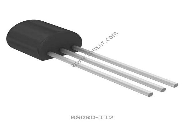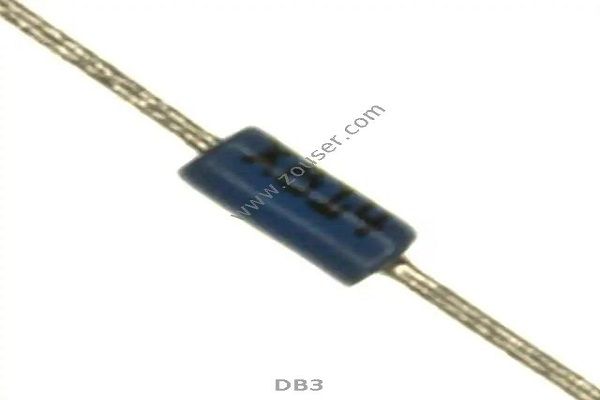
A thyristor is a semiconductor device with similar characteristics to a diode or transistor, another solid-state component made from silicon. Thus, it can be difficult to distinguish between thyristors and diodes. Additionally, there are a number of different types of thyristors available.
It can be as simple as a tiny detail that makes thyristors different from one another.
It is also possible for a given thyristor to be known by another name depending on its manufacturer.
To apply Thyristors successfully when designing circuits, it is important to know their unique characteristics, limitations, and their relationship with the circuit. For that reason, we are taking the time to sort this out so that you can choose the best thyristor for your needs.
How does a thyristor work?
Thyristors are four-layer devices containing alternating P-type and N-type semiconductors.
An anode is a positive terminal, a cathode is a negative terminal, and a gate controls the flow of current between the anode and cathode.
In addition to acting as a switch, a thyristor is capable of providing protection to circuits with high voltages and currents (up to 6000V, 4500A).
Its ability to convert rapidly from a state of conducting current to a state of non-conducting current makes it an attractive rectifier.
Furthermore, it is low maintenance and remains functional under the right conditions for a long time without developing a fault.
From burglar alarms to power transmission lines, thyristors are used in a wide variety of electric circuits.
What is the function of a thyristor?
There are three junctions in a P-N-P-N thyristor: PN, NP, and PN. If the anode is a positive terminal with respect to the cathode, the outer junctions, PN and PN, are forward-biased, while the center NP junction is reverse-biased. A thyristor is considered to be in a forward blocking state if the NP junction blocks the flow of positive current from the cathode to the anode. By contrast, the outer PN junctions block the flow of negative currents. Thyristors are in reverse blocking mode.
When a thyristor receives a sufficient signal to turn on, it can also enter a forward conducting state.
Taking a closer look at the signal and thyristor's response will help us better understand the special properties of thyristors.
A sufficient current or pulse applied to the gate terminal triggers the thyristor into a conducting state. Current flows from anode to cathode and will continue to flow even after the gate signal is removed.
By reducing the anode to cathode current below a threshold value known as the holding current, the thyristor can be unlatched.
The PNPN structure of a thyristor can be interpreted as two transistors coupled together. Thus, the collector current from the NPN transistor feeds the base of the PNP transistor. Click here: www.zouser.com

In regeneration, the loop gain is sufficiently raised to unity by applying a positive current or momentary pulse to the gate. By causing the NPN transistor to conduct current, the pulse causes the PNP transistor to conduct current in response. As long as the latching current is high enough to meet the unity gain criteria, the thyristor will remain in the on state, even when the initial triggering current on the gate is removed.
As a result of avalanche breakdowns of blocking junctions, thyristors can also turn on. For the thyristor to be turned on when the gate current is zero, the applied current must reach the thyristor's breakover voltage. In normal operation, a thyristor should have a breakover voltage that is more than the maximum voltage expected from the power source. This is undesirable, since breakdown damages the device. A thyristor can only be switched on with an intentional pulse applied to the gate, unless it is designed specifically to function in a breakover mode.